ManualsBay
Caterpillar Skid Street Loaders Schematic Electrical system 216B, 216B2, 226B, 226B2, 232B, 232B2, 236B, 236B2, 242B, 242B2, 246B, 248B, 252B, 252B2, 262B, 268B
Caterpillar Skid Street Loaders Schematic Electrical system 216B, 216B2, 226B, 226B2, 232B, 232B2, 236B, 236B2, 242B, 242B2, 246B, 248B, 252B, 252B2, 262B, 268B
Couldn't load pickup availability
- 100% Secure Checkout
- Instant PDF Download After Payment
- Verified Manuals
Caterpillar Skid Steer Loaders – Electrical System
📌 Applicable Models:
216B, 216B2
226B, 226B2
232B, 232B2
236B, 236B2
242B, 242B2
246B, 248B
252B, 252B2
262B, 268B
These models use a standard 12V DC electrical system, powered by a battery and managed by an ECM (Electronic Control Module). The system is designed to control, protect, and monitor the machine’s electrical components.
🧩 Key Components and Functions
1. Battery
A 12V battery supplies power to the entire electrical system.
Includes a 70A main fuse and a 15A auxiliary fuse for circuit protection.
2. Key Switch / Ignition
Turns the system ON/OFF.
Sends power to the Main Power Relay when turned ON.
3. Main Power Relay
Distributes power from the battery to critical systems (ECM, starter motor, HVAC, etc.).
Controlled by the ignition key switch.
4. Machine ECM (Electronic Control Module)
The brain of the system.
Controls engine functions, safety systems, alarms, and hydraulic responses.
Receives signals from sensors (e.g., oil pressure, temperature).
Sends control signals to actuators (e.g., relays, solenoids).
5. Starter Motor Circuit
Engaged by the ECM when the start signal is received from the key switch.
Draws high current directly from the battery to crank the engine.
6. HVAC Controller (Heating, Ventilation, Air Conditioning)
Controls cabin comfort features (blower, heater, AC).
Operates via signals from the ECM.
7. Alarm System
Sounds warning signals for critical conditions (engine oil pressure, overheat, system faults).
Triggered by ECM based on sensor inputs.
8. Sensors
Engine Oil Pressure Sensor
Monitors oil pressure and sends feedback to ECM.
Coolant Temperature Sensor
Monitors engine coolant temperature.
Hydraulic Lockout Switches
Ensures hydraulic system is inactive during start or fault conditions.
9. Grounding Points
Several grounding points are located on the frame and chassis.
Ground is essential for completing all electrical circuits.
10. Auxiliary Connectors
For external accessories like trailer lights, beacons, and tools.
Controlled through separate relays.
⚙️ How the System Works (Simplified Flow)
Key Turned ON:
Power flows from battery → ignition switch → main power relay → ECM and control circuits.
Start Engine:
ECM checks safety switches (neutral, hydraulic lockout).
Sends signal to starter relay → engages starter motor → cranks engine.
Engine Running:
ECM controls fuel injection, monitors sensors.
ECM enables HVAC, lighting, alarms as needed.
Alternator charges battery and powers system.
Shutdown:
Key OFF → Main power relay opens → ECM powers down.
🛡️ Safety & Diagnostic Features
ECM stores diagnostic fault codes.
Alarm triggers for low oil pressure, over-temperature, or system failure.
Lockout systems prevent accidental hydraulic movement during startup or servicing.
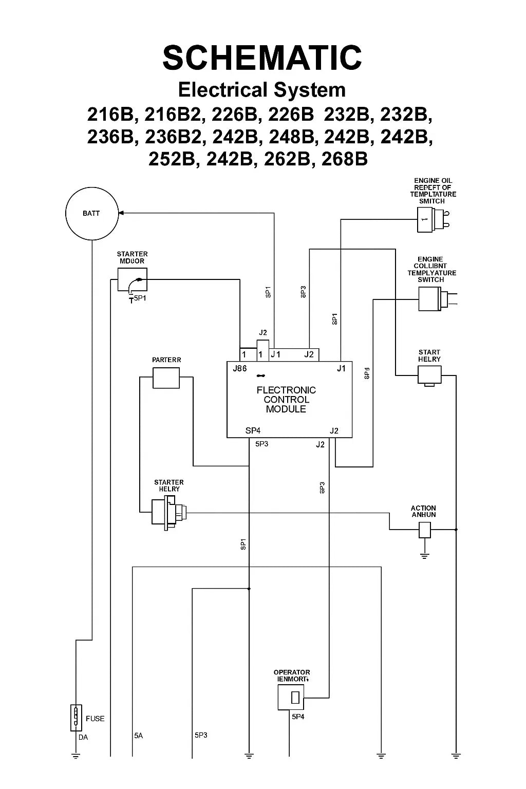
📄 Wiring Diagram (Schematic) Reference
The schematic includes:
Labeled connectors (e.g., C1, C2)
Signal paths (dashed/solid lines)
Standard symbols for relays, resistors, fuses, switches, grounds
All component pin numbers and their logical flow
Share